
© Tillypad 2008-2014
Table type images are managed in the and editor windows.
These windows are opened from the context menu of the Specification panel.
You can open the editor window by using the command. From here, you can modify attributes of one or more images that illustrate table statuses.
If one item is selected in the specification, the editor window opens.
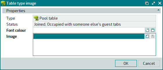
Window fields:
Type is the name of the table type to which the image is added.
This field is read-only. The field displays the table type name as specified in the data grid of the Properties panel in the window.
Status designates the status of a given table.
This field is read-only. The field displays the value as specified in the data grid of the Specification panel in the window.
Font colour indicates the font colour used to display messages on the table type image.
Image is a combo box that contains both the image itself and its file characteristics (name, resolution, and size). This is a required field.
These images are used to display the seating layout on the POS terminal screen and in the monitoring window.
You can select the image files in the standard window. To enter the name of the image file, press the selection button in the Image field.
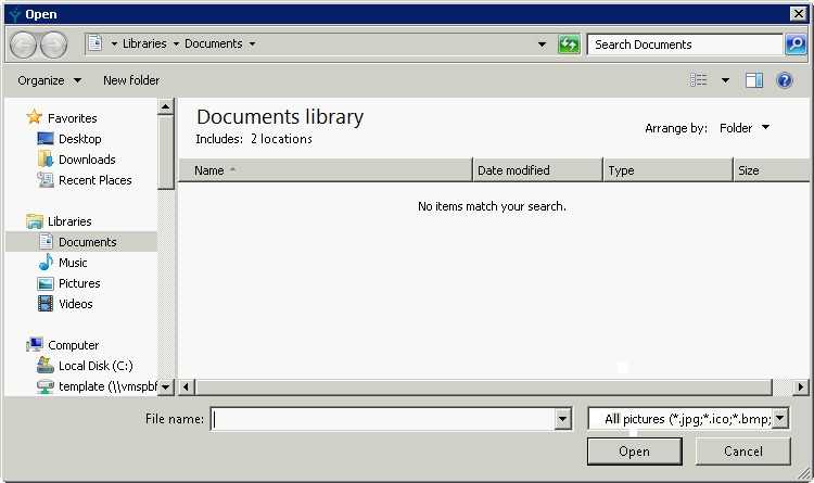
The window allows you to select the required image file from a previously created folder, e.g. Tables. Pressing the button will add the name of the file as well as its parameters and the image contained within it to the Image field.
If an image for the table type has already been added to the directory, the editor window will have the following appearance.
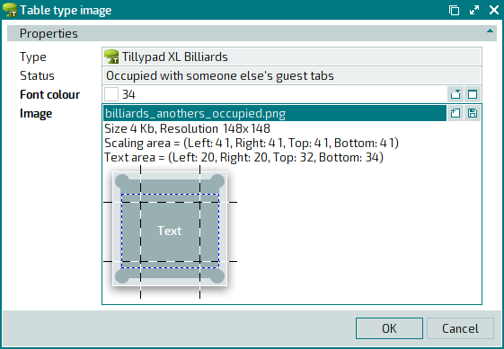
On the table type image, dash lines determine text and scaling areas.
The text area is limited by the blue dash line. The text that appears on the table type image is located in this area. Horizontally, the text is aligned by the centre; vertically, it is aligned by the height of the area. To relocate the text area, place the cursor inside it, click and hold the left mouse button and drag the area to the desired location.
To change the size of the text area, place the cursor on the border or corner of the area, click and hold the left mouse button and change the size of the area.
The scaling area is lined out with a black dash line. It divides the image into 9 parts: central, 4 corner, 2 side, the top and bottom areas. When you change the size of the image on the seating and device layout, both the width and the height of the central area are modified, but only the width of the top and the bottom areas are altered, and only the height of the side areas are changed.
To edit the scaling area borders, place the cursor on the border, click and hold the left mouse button and drag the border.
Click to save data. Selecting will close the window without saving data.
The editor window for multiple table type images opens if two or more items are selected for editing in the specification data grid. The name of the editor window changes to . A panel with a list of the selected items is added to the window. The names of the files that contain the table state images are specified in brackets.